Sisyphus Plans for the Future
The immediate plan is to create a demonstration 200 MWH system and expand it to a fully commercial 1000 MWH system. Beyond that, we plan to sell additional commercial systems throughout the U.S.
Immediate Plan
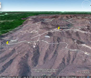
The figure to the right shows a view of the proposed site for the demonstration Sisyphus system. The line between the yellow pins is the TVA right of way for power line down from the wind farm on top of Buffalo Mountain. The lower storage yard will be sited at the lower yellow pin. The upper storage yard will be sited in the flat area below the upper storage pin.
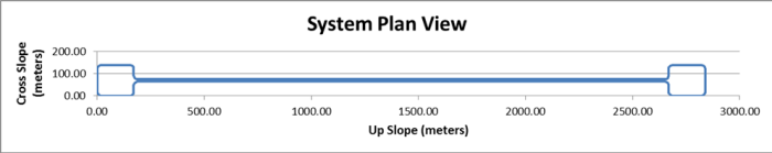
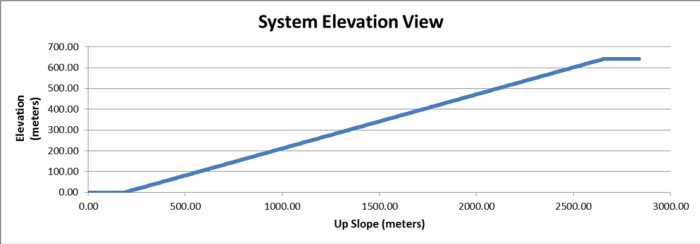
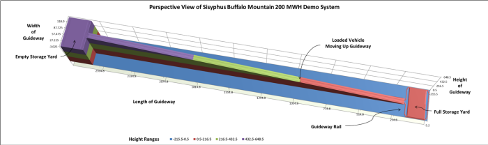
The three figures below show schematic views of the proposed system. The first figure is a plan view, showing the relative sizes of the storage yards and the guideway linking them, with the lower yard to the left. The second figure is an elevation view, showing the average slope between the storage yards. The third figure is a perspective view of the system (from the "other side," with the lower storage yard to the right and the upper storage yard to the left).
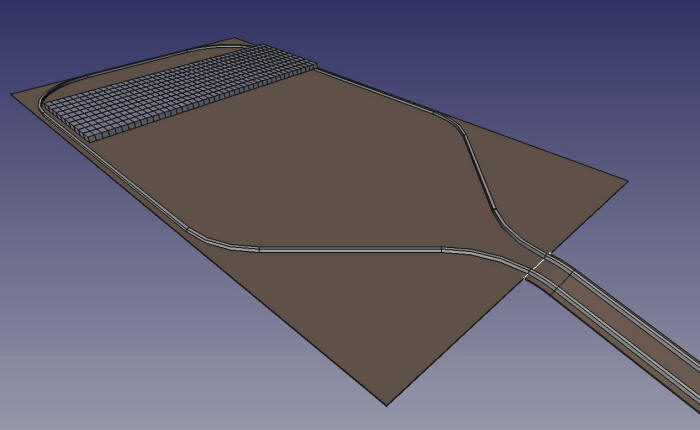
The three figures below are computer generated illustrations of the demonstration system. The first figure shows the lower storage yard, containing a number of blocks. The platforms holding the blocks are not shown. A single block is shown in the foreground to illustrate the shape of a block. An empty vehicle is shown descending the slope. Ahead of it are two empty vehicles moving around the storage yard preparatory to loading blocks. One vehicle with a block on it is shown leaving the storage yard.
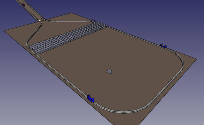
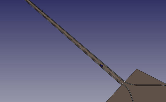
The second figure shows a section of the guideway connecting the two storage yards. The empty vehicle approaching the lower storage yard is shown in the foreground. A loaded vehicle is shown on the upper part of the slope, traveling to the upper storage yard.
The third figure shows the upper storage yard with a number of blocks already stored there. Although there would be several vehicles present in the actual system, none are shown here.
The construction of the demonstration (200 MWH) system will proceed in phases, as shown in the table below. Upon completion of the demonstration system, it will be upgraded to a full commercial storage system with 1000 MWH capacity.
| Phase | Definition | Goal | Labor Costs ($M) |
Material Costs ($M) |
Total Costs ($M) |
Duration |
| 0 | Order high temperature superconducting wire | Negotiate price and order high temperature wire. Configure working areas for later phases. Refurbish low temperature modules for demonstrations. Perform preliminary engineering. | $ 1.0 | $ 1.3 | $ 2.3 | 9 months |
| 1 | Production-scale component design and test | Establish operating parameters for load-bearing magnets and guideway (calibrate tons/magnet). Engineer the magnet modules. Includes production of two full-sized lift modules and a full-sized guideway section. | $ 1.1 | $ 0.5 | $ 1.6 | 12 months |
| 2 | Full vehicle test | Statically lift 100 ton block and measure reliability/performance parameters. Establish Maglev 2000 TRL 4. Construct short (~100 meters) angled guideway section, with power generation components. Lift block with vehicle; load block onto vehicle from storage yard; and unload block from vehicle to storage yard. Establish Sisyphus TRL 4. | $ 0.9 | $ 6.7 | $ 7.6 | 12 months |
| 3 | Full-scale mini-system | Produce a full-scale, working mini-system: two vehicles and 800m of guideway on an incline, half of which is power generating. Establish Sisyphus TRL 5. | $ 0.7 | $ 8.1 | $ 8.8 | 12 months |
| 4 | 200 MWH Demo System | Produce a small production system. Establish Sisyphus TRL 6. | $ 4.1 | $ 62.6 | $ 66.7 | 12 months |
| Total Demo | $ 7.8 | $ 79.2 | $ 87.0 | 4.75 years | ||
| 5 | 1000 MWH System | Produce a full size production system. Establish Sisyphus TRL 9. | $ 7.2 | $ 98.2 | $105.4 | 12 months |
| Grand Total | $ 15.0 | $177.4 | $192.4 | 5.75 years |
Future Plans
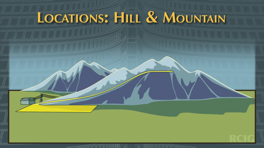
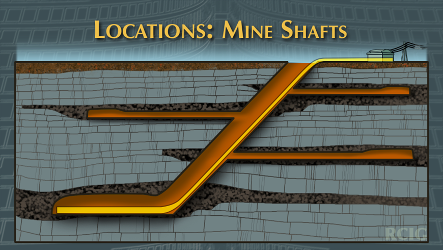
The demonstration system will be built on a mountain with a 640 meter difference in elevation between the lower and upper storage yards. This elevation difference is at the lower end of the range of profitable systems. Larger elevation differences will yield more stored energy per block and can be built on almost any large hill or mountain, as depicted in the left-hand figure below. However, a hill or mountain is not required. All that is required is the elevation difference and a path between them. As shown in the right-hand figure below, mine shafts, of which there are many in the U.S. (including in flat places like Kansas) provide opportunities for Sisyphus energy storage systems. The initial Sisyphus system has a 26% grade (about 14.5 degrees); however, this is not a limiting factor. The superconducting magnets are strong enough to negotiate vertical shafts (90 degrees), although the guideway would require redesign to handle the situation.